Hệ số cos phi trong điện lực là gì? Nguyên nhân hệ số cos phi giảm
Tóm tắt nhanh:
- Cos phi (PF) là tỷ lệ giữa công suất hữu ích (P) và công suất toàn phần (S), thể hiện hiệu quả sử dụng điện.
- Cos phi càng thấp → càng hao tổn điện năng, dễ bị phạt và gây quá tải thiết bị.
- Nguyên nhân giảm cos phi khi lắp điện mặt trời: nguồn NLMT chỉ phát công suất P, không bù công suất phản kháng Q.
- Hệ thống tụ bù không phù hợp hoặc không đủ công suất khi có thêm điện mặt trời.
- Bộ điều khiển tụ bù hoạt động sai do không nhận diện đúng chiều dòng điện.
- Sai vị trí đấu nối hoặc đặt CT không đúng làm sai số đo và bù.
- Khi P từ lưới giảm nhưng Q không đổi → cos phi tổng bị giảm mạnh.
- Ví dụ thực tế: cos phi có thể giảm từ 0.95 xuống 0.77 sau khi lắp NLMT.
- Giải pháp: cho inverter bù Q, tối ưu tụ bù, hoặc chỉnh lại vị trí đấu nối/CT.
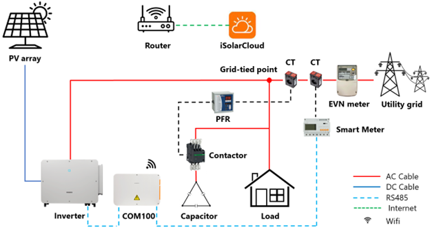
Hệ số cos phi của nhà máy bị giảm là một trong những vấn đề thường gặp phải khi lắp đặt đấu nối hệ thống điện năng lượng mặt trời hòa lưới vào hệ thống điện của các nhà máy đang vận hành. Hệ số cos phi thấp sẽ dẫn tới tăng tổn hao năng lượng, hao mòn các thiết bị dây dẫn, trạm biến áp, tác động xấu đến hệ thống lưới điện quốc gia và có thể bị phạt hệ số cos phi thấp từ nhà cung cấp điện.
1. Hệ số cos phi là gì?
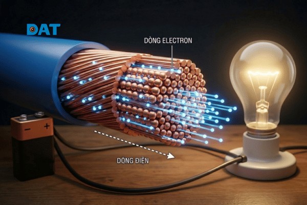
Cos phi (còn gọi là hệ số công suất hoặc hệ số PF) là tỷ số giữa công suất tác dụng và công suất biểu kiến của thiết bị điện. Nó thể hiện mức độ hiệu quả sử dụng điện năng trong hệ thống.
Công thức cơ bản: Cos φ = P/S
Trong đó:
- P (công suất tác dụng): đo bằng W hoặc kW
- S (công suất biểu kiến): đo bằng VA hoặc kVA
- Q (công suất phản kháng): đo bằng Var hoặc kVar
Công thức mở rộng: P = U × I × Cos φ
Do P luôn nhỏ hơn S, nên giá trị cos phi không bao giờ chạm ngưỡng bằng 1, chỉ có thể xấp xỉ hoặc tiến dần đến 1.
2. Nguyên nhân hệ số cos phi giảm
- Hệ thống tụ bù hiện hữu của nhà máy công suất không đủ để bù cos phi khi hệ thống NLMT hòa lưới.
- Công suất cấp tụ bù của hệ thống tụ bù nhà máy quá lớn, không nhuyễn làm cho bộ điều khiển tụ bù không hoạt động hiệu quả (đóng thêm cấp tụ bù thì dư mà ngắt ra thì thiếu).
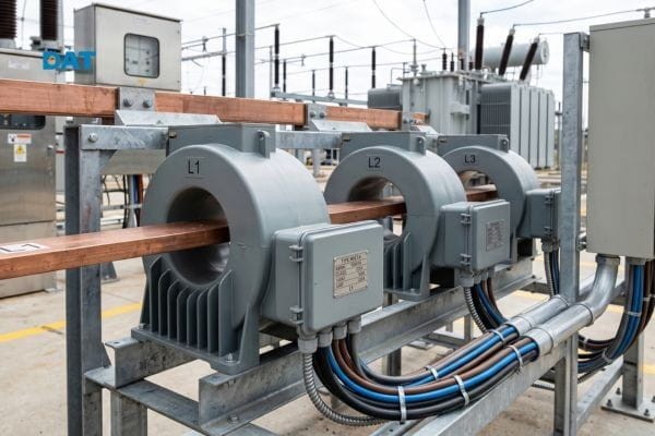
- Bộ điều khiển tụ bù không có chức năng hỗ trợ khi hệ thống NLMT hòa lưới. Bộ điều khiển tủ tụ bù không xác định được chiều dòng điện lưới cấp xuống tải hay NLMT trả về lưới để điều khiển tụ bù đóng chính xác.
- Điểm đấu nối hòa lưới hệ thống điện NLMT nằm dưới vị trí CT của bộ điều khiển tụ bù.
*** Bài toán ví dụ
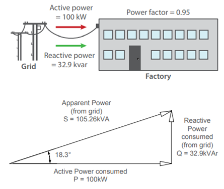
- Xét trường hợp nhà máy chưa lắp đặt hệ thống NLMT:
Nhà máy hoạt động khi chưa lắp hệ thống năng lượng mặt trời, 100% điện năng được lấy từ lưới điện.
| Công suất tác dụng (P) | Công suất phản kháng (Q) | Công suất biểu kiến (S) | Hệ số công suất (Cos phi) |
| 100kW | 32.9kVAr | 105.26kVA | 0.95 |
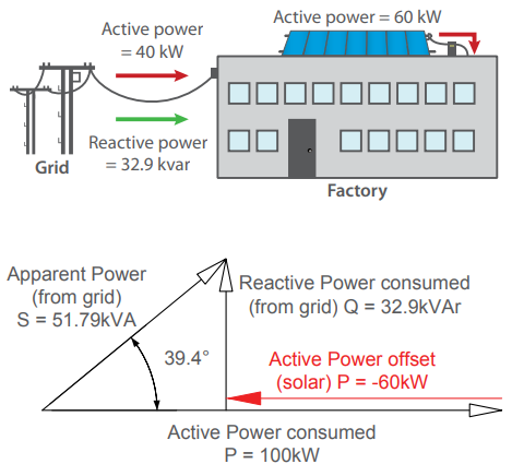
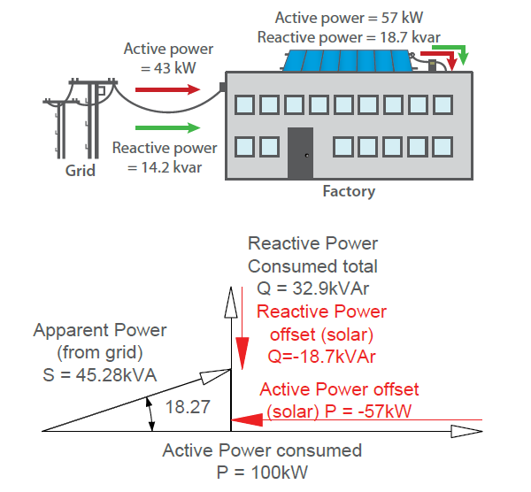
- Xét trường hợp đã lắp hệ thống NLMT: Hệ thống NLMT chỉ phát công suất tác dụng (P)
Trong trường hợp công suất tiêu thụ của nhà máy không đổi (P=100kW và Q=32.9kVAr), nếu nhà máy này lắp đặt một hệ thống NLMT phát ra công suất tác dụng (P) 60kW với hệ số công suất (cos phi) bằng 1, thì chỉ có công suất tác dụng (P) lấy từ lưới điện giảm do hệ thống NLMT hỗ trợ. Lúc này, công suất tác dụng (P) lấy từ lưới điện chỉ là 40kW trong khi công suất phản kháng (Q) lấy từ lưới không đổi là 32.9kVAr. Điều này làm giảm hệ số công suất (cos phi) của hệ thống xuống còn 0.77.
| Công suất tác dụng (P) lấy từ lưới điện | Công suất tác dụng (P1) do NLMT cung cấp | Công suất tác dụng (P2 = P+P1) của tải tiêu thụ | Công suất phản kháng (Q) lấy từ lưới điện | Công suất biểu kiến (S) lấy từ lưới điện | Hệ số công suất (Cos phi = P/S) |
| 40kW | 60kW | 100kW | 32.9kVAr | 51.79kVA | 0.77 |
3. Phương án xử lý vấn đề giảm hệ số công suất khi hệ thống NLMT hoạt động
3.1. Cài đặt để hệ thống NLMT phát cả P và Q với giá trị cos phi cố định là 0.95
– Cài đặt hệ thống NLMT phát điện với hệ số công suất phù hợp để các Inverter vừa phát ra công suất tác dụng (P) và công suất phản kháng (Q), làm giảm lượng công suất tác dụng (P) và công suất phản kháng (Q) lấy từ lưới điện. Do đó, hệ số công suất (cos phi) được duy trì như hiện trạng ban đầu khi nhà máy chưa lắp hệ thống NLMT.
– Ưu điểm: dễ thực hiện, không thay đổi vị trí hòa lưới hay dời vị trí CT của bộ điều khiển tụ bù.
– Nhược điểm: Ảnh hưởng đến sản lượng phát điện do hệ thống NLMT phát ra một lượng công suất phản kháng (Q) và làm giảm hệ số PR (Performance Ratio) của hệ thống điện NLMT.
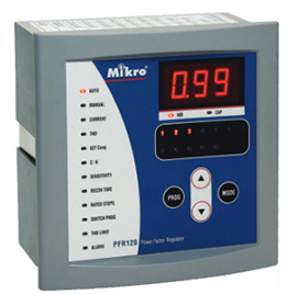
3.2. Cài đặt thông số cos phi lên 0.99, chọn chế độ hoạt động Four – quadrant cho bộ điều khiển tụ bù:
– Thay đổi thông số cài đặt Set cos phi cho bộ điều khiển tụ bù với giá trị cos phi = 0.99 và bật chế độ Four – quadrant. Chế độ Four – quadrant cho phép bộ điều khiển tụ bù hoạt động ở cả chế độ thu và phát công suất. Nếu cài đặt chế độ này phải đảm bảo cực tính của CT lắp đúng, nếu sai cực tính thì chức năng này sẽ không hoạt động được. Bộ điều khiển tụ bù sẽ đóng nhiều cấp tụ bù hơn để phát ra lượng công suất phản kháng nhiều hơn nhầm nâng cao giá trị công suất phản kháng (cos phi) của hệ thống điện.
– Trong trường hợp hệ thống tụ bù vẫn không đủ để nâng cos phi của hệ thống lên 0.9 thì cần tính toán để lên phương án lắp bổ sung thêm tụ bù.
– Ưu điểm: dễ thực hiện.
– Nhược điểm: dung lượng tụ bù có thể không đủ để nâng hệ số công suất (cos phi) của hệ thống điện lên 0.9 hoặc cấp tụ bù quá lớn và không nhuyễn có thể làm cho bộ điều khiển tụ bù không điều khiển tối ưu quá trình đóng mở các cấp tụ bù.
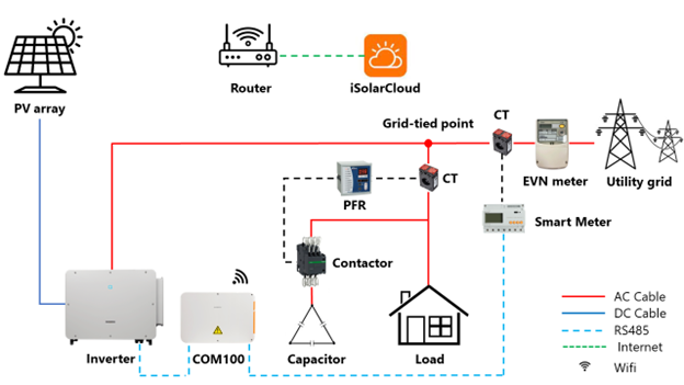
3.3. Thay đổi vị trí điểm đấu nối hòa lưới của hệ thống NLMT cho phù hợp
– Điểm đấu nối hòa lưới chưa phù hợp là nguyên nhân chính gây ra hiện tượng giảm giá trị hệ số công suất (cos phi) của hệ thống điện khi hệ thống NLMT hòa lưới.
– Điều chỉnh điểm hòa lưới nằm phía trên CT của bộ điều khiển tụ bù hoặc dời CT của bộ điều khiển tụ bù xuống dưới điểm hòa lưới của hệ thống NLMT, sẽ khắc phục được vấn đề giảm giá trị hệ số công suất (cos phi) khi hệ thống NLMT hòa lưới.
– Ưu điểm: giải quyết được vấn đề giảm hệ số công suất (cos phi) mà không làm ảnh hưởng đến sản lượng phát điện của hệ thống NLMT.
– Nhược điểm: khó khăn trong việc thay đổi vị trí hòa lưới hoặc thay đổi vị trí CT của bộ điều khiển tụ bù.
Chúng ta có thể thấy rằng:
- Hệ thống điện NLMT đóng vai trò là nguồn chứ không phải là tải tiêu thụ nên không tiêu thụ công suất phản kháng (Q).
- Để phòng tránh trường hợp bị giảm cos phi của nhà máy sau khi lắp đặt hệ thống điện NLMT, chúng ta cần lưu ý những điểm sau:
– Thu thập đầy đủ các thông tin về hệ thống tụ bù (dung lượng, số cấp tụ bù), hệ số cos phi của nhà máy tại các thời điểm và số cấp tụ bù đang đóng tương ứng với giá trị cos phi tại thời điểm đó.
– Khảo sát kỹ vị trí đấu nối hòa lưới của hệ thống điện NLMT xem điểm hòa lưới có nằm phía trên CT của bộ điều khiển tụ bù được hay không. Nếu trong trường hợp bất khả kháng, vị trí hòa lưới hệ thống điện NLMT không thể nằm ở phía trên CT của bộ điều khiển tụ bù thì cần lên phương án để xử lý như theo các phương án đã nêu trên.
Quý Khách hàng, Quý Đối tác muốn tư vấn thêm về các giải pháp điện mặt trời trọn gói, toàn diện và hiệu quả, vui lòng gọi ngay Hotline 1800 6567 (miễn phí cước) để được DAT Group đồng hành, hỗ trợ 24/7.